
How to install a natural gas pressure regulator?
How do you install a natural gas pressure regulator? The following provides installation and startup instructions for Itron’s B-series regulators (Models B42, B57, B58, B31, B34S, B34, B38, B35, B36, and B56).
In the market for a regulator?
Gas Regulator Installation Requirements
Before beginning, the installer must follow all of the company’s safety and personal protection equipment (PPE) policies, corporate guidelines, and these instructions when installing and repairing a natural gas regulator.
- The B-series regulator’s maximum inlet pressure depends on the orifice size and model designation. Non-relief models are limited to 60 psig maximum inlet pressure unless additional safety devices are used (as outlined in the DOT code: OPS, Part 192, Section 192.197).
- B-series regulators for liquid petroleum gases should be restricted to second-stage pressure reduction in the gaseous phase.
- If the B57 regulator’s diaphragm case is loosened from the valve body using the union nut, the torque specification for tightening the union nut is 35-50 ft·lb. Tighten the union nut to the correct torque specification anytime the nut is loosened.
How to install a gas regulator?
Outdoor Installation
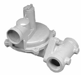 |
| Itron B-42 Regulator |
- Always position the regulator vent so moisture (rain, snow) or foreign particles cannot enter the vent opening. Itron recommends placing the vent downward.
- Locate the vent away from building eaves, window openings, or building air intakes.
- Mount the regulator vent above the site’s expected snow level when appropriate.
Indoor Installation
- The shortest pipe length
- The fewest possible pipe elbows
- A pipe diameter equal to the vent size (or larger)
Startup Procedure (all Itron models)
To start up the B-series regulator
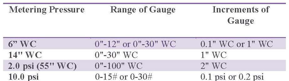
- Mount a pressure gauge downstream of the regulator to monitor the downstream pressure.
- With the downstream pressure valve closed, slowly open the inlet valve. The outlet pressure should rise slightly more than the set point. Note: For B31 RAS models, remove the seal cap and pull it up on the spring housing stem to reset the shut-off valve. Release the stem. This procedure allows gas to flow through the regulator. Downstream pressure should rise to the regulator’s set point.
- Verify there are no leaks and that all connections are tight.
- The regulator was pre-set at the factory to match order specifications. If necessary, adjust the pressure (outlet) by removing the seal cap on the top of the spring housing and rotating the adjustment screw inside the spring housing.
Models 842, B57, B58, B31, B34S, B35, B56, and B36: large flat-head screwdriver
Models 834 and 838: 9116″ socket and ratchet
Model RB4000: adjustment wrench (ltron part number 799056)
Rotate the adjustment screw clockwise to raise the outlet pressure.
Rotate the adjustment screw counter-clockwise to lower the outlet pressure.
Regulator Distributor
More information is available on Itron’s regulators.


What is the max distance can a natural gas regulator be from a rooftop unit